
Sheet metal bending is a fundamental process in metal fabrication, involving the deformation of metal sheets into desired shapes using press brakes and dies. Understanding the types of bending dies, size calculations, and operational steps is crucial for achieving accurate and efficient bends. This article delves into the details of sheet metal bending, focusing on die selection, size calculation, and operational procedures.
Types of Bending Dies
Sheet metal bending utilizes various types of dies to achieve different bending results. The primary categories are:
1. Standard Dies
Used for standard bends, including both right-angle (90 degrees) and non-right-angle bends.
2. Special Dies
Designed for bending specific structural components, such as offset bends and dead-edge bends.
Die Selection Based on Material Thickness
The selection of bending dies, particularly the V-shaped bottom die, depends on the thickness of the material being bent. Here are general guidelines for selecting the appropriate V-groove width based on material thickness:
- For 0.5 to 2.6 mm thickness: Use a V-groove width of 6 times the material thickness (6t).
- For 3 to 8 mm thickness: Use a V-groove width of 8 times the material thickness (8t).
- For 9 to 10 mm thickness: Use a V-groove width of 10 times the material thickness (10t).
- For thickness above 12 mm: Use a V-groove width of 12 times the material thickness (12t).
Bending Size Calculation
Accurate size calculation is essential for achieving precise bends. Here’s how to calculate the developed length for different types of bends:
Right-Angle Bends (90 Degrees)
For right-angle bends, the bend allowance formula is used:
Bend Allowance = Material Thickness * 0.35
The developed length (L) can be calculated as:
Developed Length (L) = (Bend Length + Bend Length) + (2 * Bend Allowance)
Non-Right-Angle Bends (Less than 90 Degrees)
For non-right-angle bends, the bend allowance is different:
Bend Allowance = Material Thickness * 0.18
The developed length (L) is calculated as:
Developed Length (L) = (Bend Length + Bend Length) + (2 * Bend Allowance)
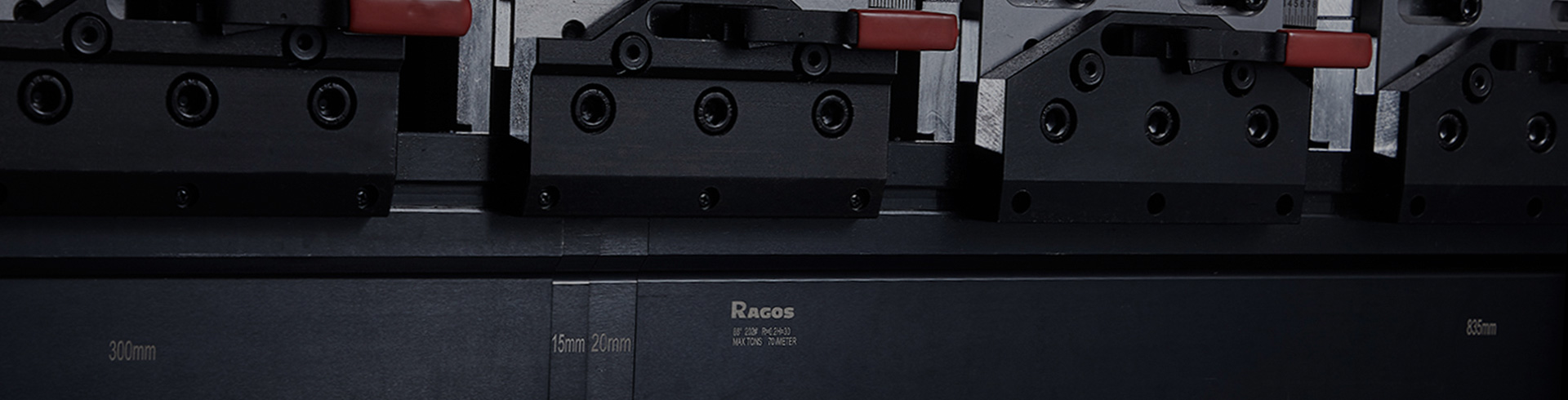
Combination of Dies
To accommodate various workpiece sizes, press brake dies are often segmented into different lengths, typically with a standard length of 835 mm. These segments can be combined to handle diverse bending requirements.
Operational Steps for Using a Press Brake
The following steps outline the typical procedure for operating a press brake:
1. Positioning the Workpiece: Place the workpiece on the press brake.
2. Engaging the Brake Shoe: Use the lift rod to raise the brake shoe.
3. Aligning the Workpiece: Slide the workpiece to the appropriate position.
4. Lowering the Brake Shoe: Lower the brake shoe onto the workpiece.
5. Applying Force: Apply force to the bending lever to achieve the desired bend.
Minimum Bending Radius
The minimum bending radius is influenced by the metal’s ductility and thickness. It’s crucial to adhere to these minimums to avoid cracking and other defects.
Sheet Metal Bending and Flattening Calculations
Different methods are used for calculating the bending and flattening of sheet metal, depending on the bend radius:
For Small Radius Bends
The bend deduction method is commonly used. For example:
- For a single thickness: Deduct 1.75 times the material thickness.
- For double thickness: Deduct 3.5 times the material thickness.
For Large Radius Bends
When dealing with larger radii, use the centerline (median line) of the bend to calculate the developed length.
PROE Bending Coefficient Calculation Formula
In software like PROE, the bending coefficient is used to calculate the developed length during the bending and flattening processes. The formula is:
L = 0.5π × (R + K × T) × (θ / 90)
Where:
- L = Developed length of the sheet metal
- R = Inside radius of the bend
- T = Material thickness
- θ = Bend angle
- K = Stretch factor of the material during bending, typically between 0 and 1
FAQs
What are the different types of bending dies used in sheet metal bending?
Standard dies for right-angle and non-right-angle bends, and special dies for specific structural components.
How do I select the appropriate V-groove width for bending dies?
Select the V-groove width based on material thickness, typically 6-12 times the thickness.
How is the developed length calculated for right-angle bends?
Use the formula: L = (Bend Length + Bend Length) + (2 * Bend Allowance).
What factors influence the minimum bending radius?
The metal’s ductility and thickness determine the minimum bending radius.
How are bending and flattening calculations performed for large radius bends?
Use the centerline (median line) method to calculate the developed length for large radius bends.
What is the bending coefficient formula in PROE for sheet metal?
The formula is: L = 0.5π × (R + K × T) × (θ / 90).
Conclusion
Mastering the process of sheet metal bending involves understanding the types of dies, performing precise size calculations, and following systematic operational steps. By adhering to these guidelines, fabricators can achieve accurate and efficient bends, enhancing the quality of their metal products.
Types of Bending Dies
Sheet metal bending utilizes various types of dies to achieve different bending results. The primary categories are:
1. Standard Dies
Used for standard bends, including both right-angle (90 degrees) and non-right-angle bends.
2. Special Dies
Designed for bending specific structural components, such as offset bends and dead-edge bends.
Die Selection Based on Material Thickness
The selection of bending dies, particularly the V-shaped bottom die, depends on the thickness of the material being bent. Here are general guidelines for selecting the appropriate V-groove width based on material thickness:
- For 0.5 to 2.6 mm thickness: Use a V-groove width of 6 times the material thickness (6t).
- For 3 to 8 mm thickness: Use a V-groove width of 8 times the material thickness (8t).
- For 9 to 10 mm thickness: Use a V-groove width of 10 times the material thickness (10t).
- For thickness above 12 mm: Use a V-groove width of 12 times the material thickness (12t).
Bending Size Calculation
Accurate size calculation is essential for achieving precise bends. Here’s how to calculate the developed length for different types of bends:
Right-Angle Bends (90 Degrees)
For right-angle bends, the bend allowance formula is used:
Bend Allowance = Material Thickness * 0.35
The developed length (L) can be calculated as:
Developed Length (L) = (Bend Length + Bend Length) + (2 * Bend Allowance)
Non-Right-Angle Bends (Less than 90 Degrees)
For non-right-angle bends, the bend allowance is different:
Bend Allowance = Material Thickness * 0.18
The developed length (L) is calculated as:
Developed Length (L) = (Bend Length + Bend Length) + (2 * Bend Allowance)
Combination of Dies
To accommodate various workpiece sizes, press brake dies are often segmented into different lengths, typically with a standard length of 835 mm. These segments can be combined to handle diverse bending requirements.
Operational Steps for Using a Press Brake
The following steps outline the typical procedure for operating a press brake:
1. Positioning the Workpiece: Place the workpiece on the press brake.
2. Engaging the Brake Shoe: Use the lift rod to raise the brake shoe.
3. Aligning the Workpiece: Slide the workpiece to the appropriate position.
4. Lowering the Brake Shoe: Lower the brake shoe onto the workpiece.
5. Applying Force: Apply force to the bending lever to achieve the desired bend.
Minimum Bending Radius
The minimum bending radius is influenced by the metal’s ductility and thickness. It’s crucial to adhere to these minimums to avoid cracking and other defects.
Sheet Metal Bending and Flattening Calculations
Different methods are used for calculating the bending and flattening of sheet metal, depending on the bend radius:
For Small Radius Bends
The bend deduction method is commonly used. For example:
- For a single thickness: Deduct 1.75 times the material thickness.
- For double thickness: Deduct 3.5 times the material thickness.
For Large Radius Bends
When dealing with larger radii, use the centerline (median line) of the bend to calculate the developed length.
PROE Bending Coefficient Calculation Formula
In software like PROE, the bending coefficient is used to calculate the developed length during the bending and flattening processes. The formula is:
L = 0.5π × (R + K × T) × (θ / 90)
Where:
- L = Developed length of the sheet metal
- R = Inside radius of the bend
- T = Material thickness
- θ = Bend angle
- K = Stretch factor of the material during bending, typically between 0 and 1
FAQs
What are the different types of bending dies used in sheet metal bending?
Standard dies for right-angle and non-right-angle bends, and special dies for specific structural components.
How do I select the appropriate V-groove width for bending dies?
Select the V-groove width based on material thickness, typically 6-12 times the thickness.
How is the developed length calculated for right-angle bends?
Use the formula: L = (Bend Length + Bend Length) + (2 * Bend Allowance).
What factors influence the minimum bending radius?
The metal’s ductility and thickness determine the minimum bending radius.
How are bending and flattening calculations performed for large radius bends?
Use the centerline (median line) method to calculate the developed length for large radius bends.
What is the bending coefficient formula in PROE for sheet metal?
The formula is: L = 0.5π × (R + K × T) × (θ / 90).
Conclusion
Mastering the process of sheet metal bending involves understanding the types of dies, performing precise size calculations, and following systematic operational steps. By adhering to these guidelines, fabricators can achieve accurate and efficient bends, enhancing the quality of their metal products.
